15. Audio
Audio in DL20 is two separate circuits: clip audio (what plays along with the video and goes to the
audio output) and the audio input (a microphone or line input that feeds the spectrum analysis and
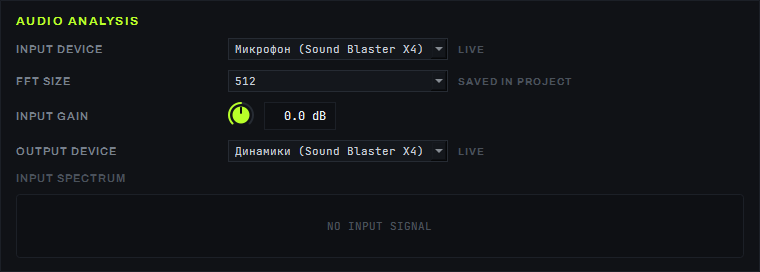
LTC reception). Both are configured in SETTINGS → the AUDIO ANALYSIS card; routing a single layer's
audio is right on its strip on the COMPOSITION screen.
Clip audio
One audio output, 48 kHz stereo float — the audio of all layers is mixed into it. A layer's audio volume is its strip's VOL × the master section's overall VOL (both are modulated like any other parameter). The output device is chosen with the OUTPUT DEVICE field in the AUDIO ANALYSIS card and is remembered in the project by name.
Audio plays only during normal playback (1×, forward): on pause and at a changed speed it is silent without clicks, and a loop turnaround (LOOP) passes without a gap in the audio.
Layer strip audio controls
On a layer's strip on the COMPOSITION screen, under the VOL knob, are three more controls for routing that specific layer's audio:
- OUT — where the layer's audio goes: MASTER (default) sends it into the common mix on the output device from AUDIO ANALYSIS; OFF turns the layer's audio off entirely; the name of a specific audio device sends this layer's audio straight to it, as a separate stream — bypassing the common mix (the device is opened separately from the main output). The layer's volume is still computed the usual way — layer VOL × master section VOL — regardless of the chosen OUT. This lets you, for example, send one layer's audio to a separate speaker without touching the overall program mix.
- CH — which channels the chosen output gets: BOTH keeps stereo, LEFT and RIGHT send a mono mixdown to a single channel on the chosen output.
- The level meter to the right of the VOL knob — a pair of bars (left/right channel) showing the live audio level of that specific layer.
Audio input and FFT
- INPUT DEVICE — the recording device (switches on the fly, status LIVE).
- FFT size — 256 / 512 / 1024 / 2048 / 4096, saved in the project; the working value 512 gives a sound → parameter delay of about 38 ms.
- Input gain — a knob from −12 to +12 dB, default 0 dB.
- OUTPUT DEVICE — the clip audio output device (see above), status LIVE.
- Input spectrum — a strip of 64 bars; while there is no signal, the caption reads
NO INPUT SIGNAL.
The audio input feeds FFT parameter modulation and LTC reception (page 12).
How to
- To send clip audio to the speaker or interface you need — pick it in the OUTPUT DEVICE field of the AUDIO ANALYSIS card.
- To adjust a specific layer's volume — turn VOL on its strip; the overall volume of the whole show is the VOL fader in the master section.
- To send one layer's audio to a separate device — pick it in that strip's OUT combo instead of MASTER; to turn the layer's audio off entirely — pick OFF.
- To send a mono mixdown to a single channel instead of stereo — pick LEFT or RIGHT in the CH combo next to OUT.
- To set up the spectrum analysis — pick INPUT DEVICE, tune FFT size and Input gain so that the Input spectrum bars move without clipping at the top of the scale.
Parameters
| Parameter | Values |
|---|---|
| Clip audio output | 48 kHz, stereo, float |
| Layer volume | layer VOL × master VOL |
| Layer OUT | MASTER / OFF / device name |
| Layer CH | BOTH / LEFT / RIGHT |
| FFT size | 256 / 512 / 1024 / 2048 / 4096 (working value — 512) |
| Sound → parameter delay (FFT 512) | ≈ 38 ms |
| Input gain | −12…+12 dB, default 0 dB |
| Input spectrum | 64 bars |
Limitations
- WASAPI loopback (capturing "what is playing in Windows" as a source) is not something standard RtAudio can do — the audio input accepts only an external signal from a physical device.